Back for part 6 of the build thread. To get back to the topic, you best browse through the last entry
As high horsepower engines should always be under supervision, I decided to add another sensor to the system.
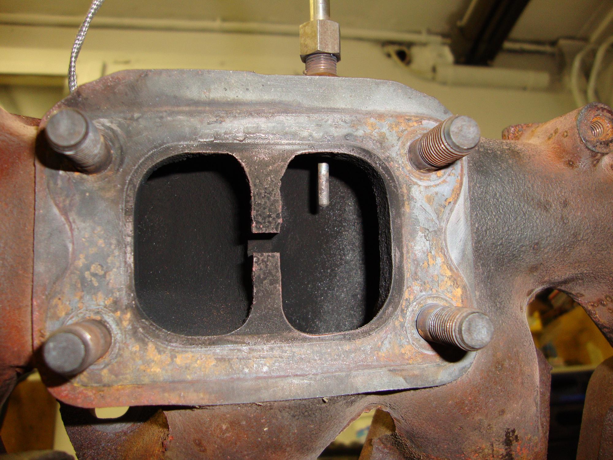
An exhaust temperature sensor to check the exhaust gases while boostin‘. Normally you would try to mount such sensor in the center of the exhaust streams from all cylinders. Since the stock RB exhaust manifold features a divided housing for the 3 front and 3 rear cylinders, this was not really possible. I did not want to drill a hole into the new turbo (which will join the two sections finally), so I had to decide for either section.
These engines usually tend to have temperature issues at the rearmost cylinder, which would then manifest in higher exhaust gas temps. So the decision was obvious to install the sensor at the rear section of the manifold.
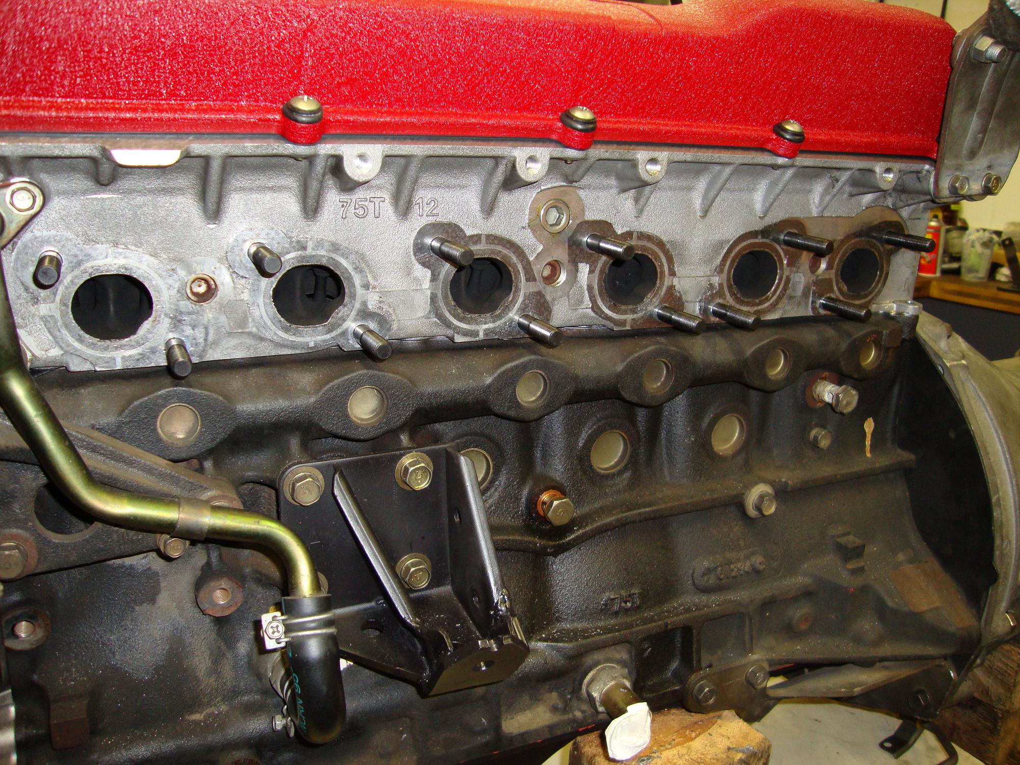
Also it is known, that the stock exhaust studs of Nissan engines are prone to break or loose themselves. My engine was no exception, I had the machine shop to drill 3 ripped-off studs out of the cylinder head. So here I installed new and upgraded studs to ensure reliability.
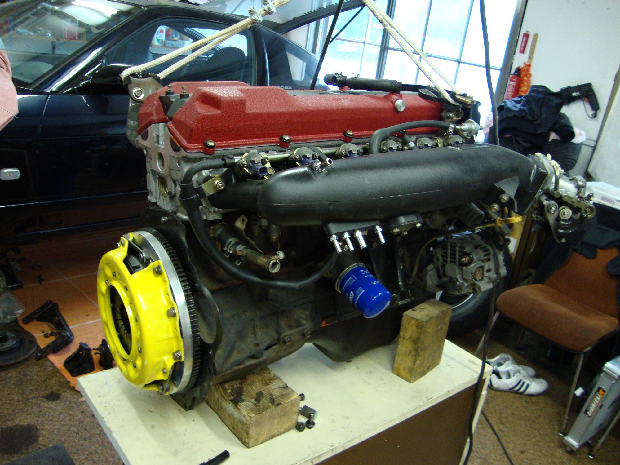
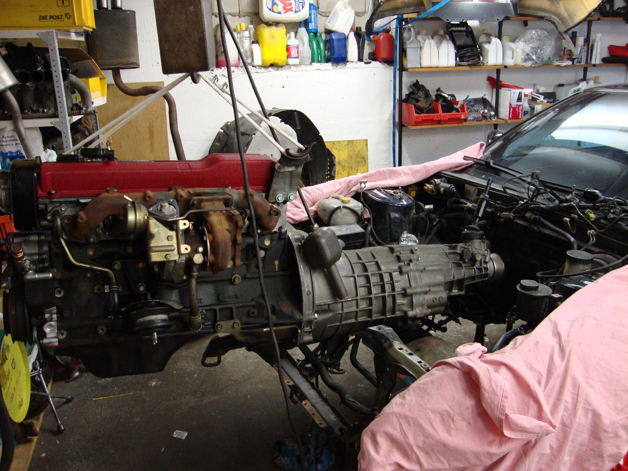
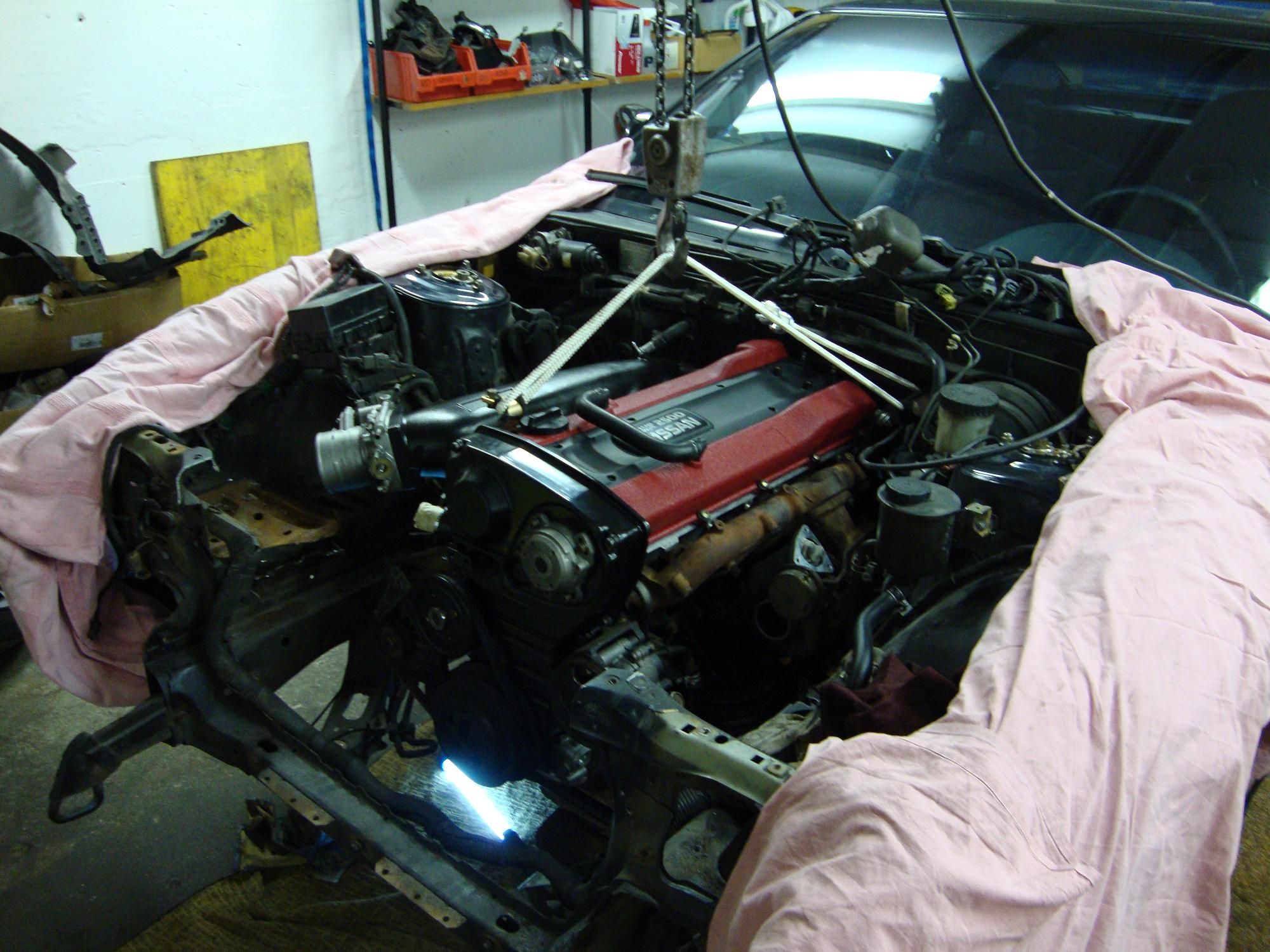
The engine now was more or less ready for a first mock-up in the bay. I bolted on the stock turbocharger, because the new one still wasn’t here.
The engine including the R33 GTS-T manual transmission was hooked-up and directed to the engine bay. As mentioned in one of the first blog entries, I had cut the front upper support member to ease access for the long and fat RB25. The supporting member and the chassis was modified to that effect, that I can properly reinstall and tighten the member after the final installation of the engine.
At the first glance, the fitment looked already promising. The engine seemed to really belong there 🙂
No major space issues (after having removed a lot of unecessary crap). But more on that later…
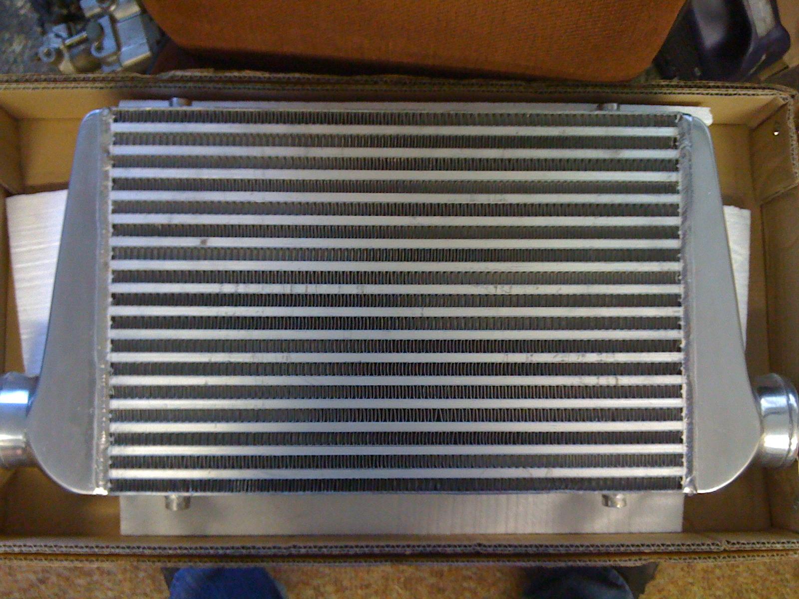
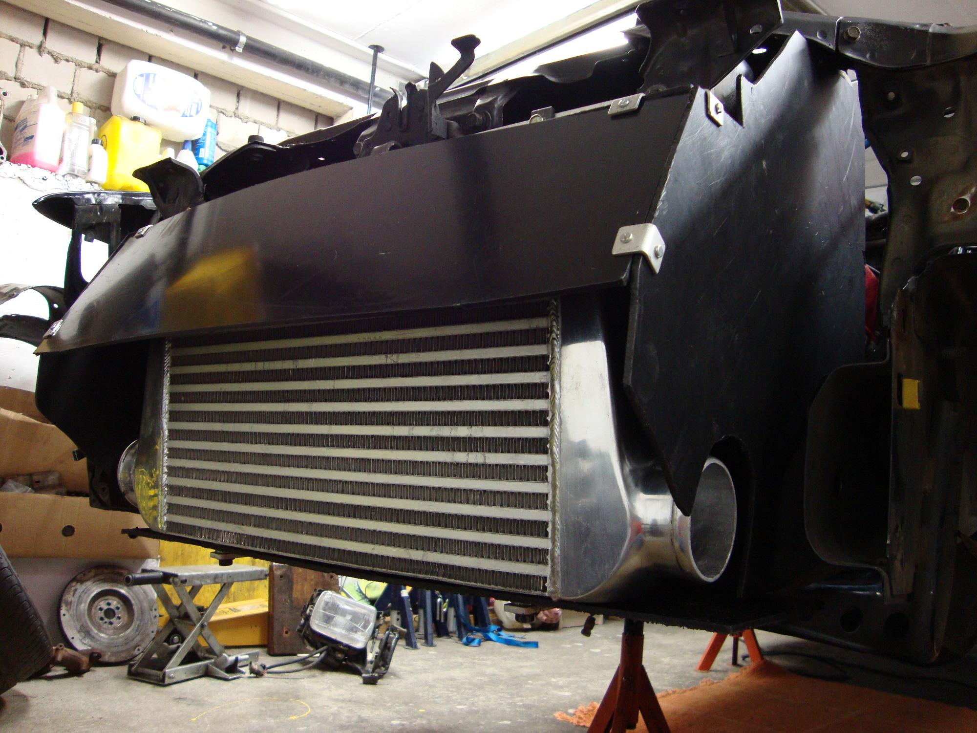
To cool down the charged air, a properly sized intercooler needed to be choosen. I know there are a lot of stories and theories on how thick/thin, long/short, wide/narrow etc. … an ideal intercooler should be sized. My personal experience lead me to the following conclusion: Install a relatively thick (80mm) and medium sized (not too big) intercooler, featuring a mesh style core (the runners of the core have a mesh inside them also). The tubing (in and out) features 3″ (75mm), which to me seemed to be a nice compromise between performance and responsiveness.
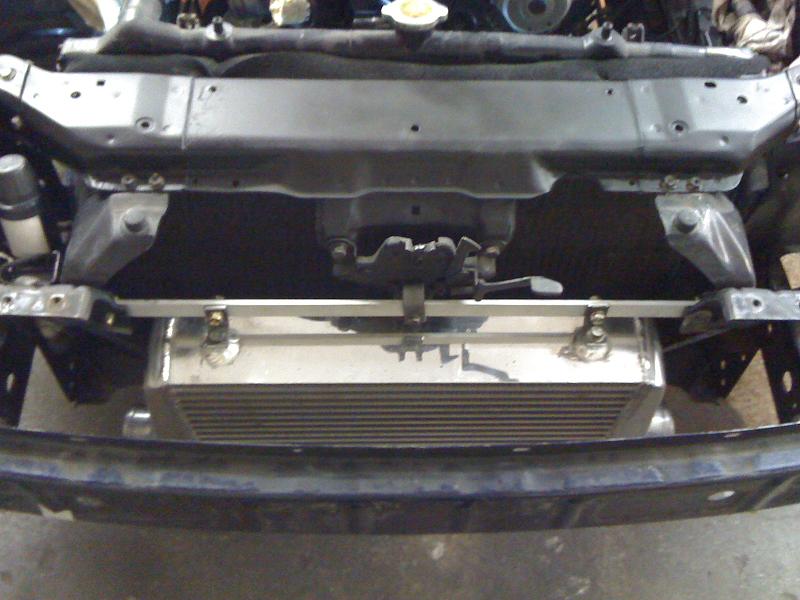
The intercooler fit in perfectly between the two main longitudal supports of the S-Chassis.
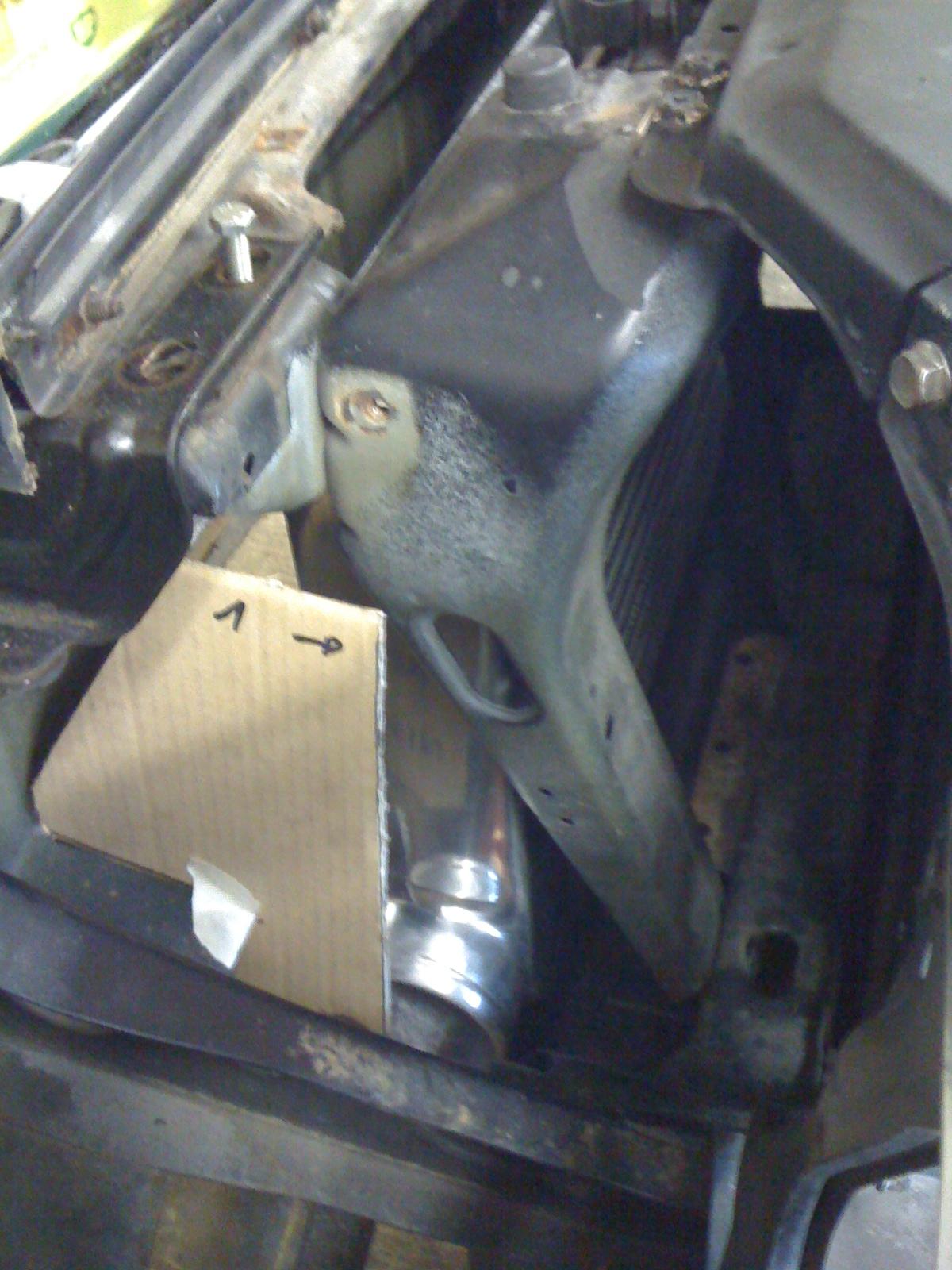
In my everpresent addiction to improvement and efficiency, I wanted the air entering the main front duct to be ideally directed through all the temperature exchanging components. Due to that, I needed to develop my own air ducting of the front. I mocked it up with the help of cardboard.
The result was really convincing. Now the air, that enters the front duct of the S13, is forced to first run through the intercooler and then through the radiator. I first thought about installing the oil cooler in between the two, but finally had a better idea.
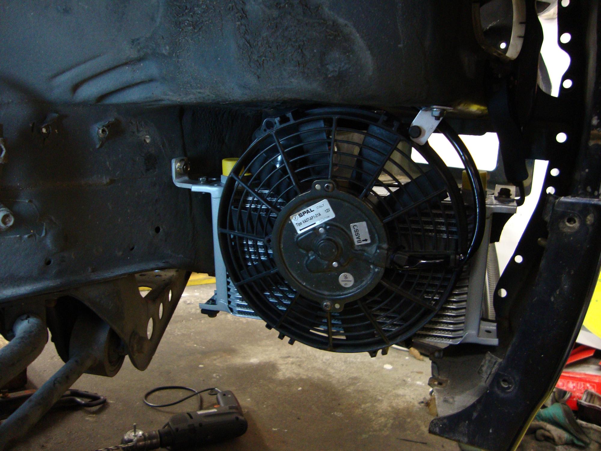
Since hard track abuse and drifting should also be possible with this setup, I wanted to get the oil cooling as effective as possible.
So I installed the oil cooler in front of the right-handside wheel, where the window washer tank used to be. A plastic tunnel from the right-hand side-duct of the S13 front bumper feeds the oil cooler with fresh air. Behind the cooler I cut out the plastic cover for the wheel arch and installed a ventilation cover. A performance fan can be switched on from the cockpit, if oil temps get too high on a hot day on the track.
Next time, more on the turbo and engine installation… 🙂
-Chris
